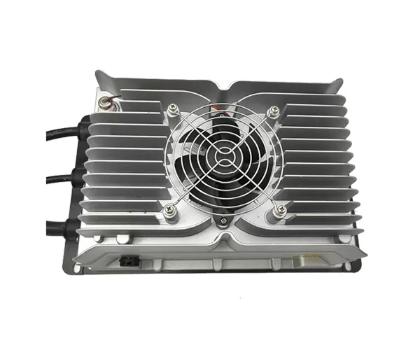
Installing a DC fast charging station is only the first step toward launching a public charging service. Before opening the site, operators must verify that electrical connections, safety protection, vehicle communication, charging performance, and backend systems all work as expected.
DC fast charger commissioning is the process of inspecting and testing installed equipment to confirm that it meets technical requirements and is ready for operation. This guide provides 10 essential commissioning tests for charging station operators, electrical contractors, and project developers to complete before public access is enabled.
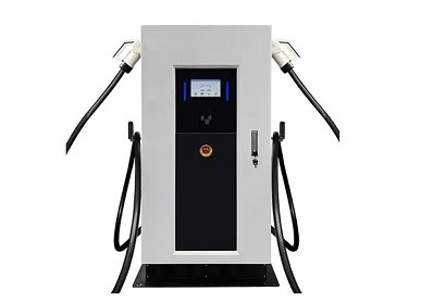
DC fast charger commissioning is the final verification process performed after installation and before a charging station enters commercial operation. It confirms that the equipment has been installed correctly, operates safely, and communicates properly with connected vehicles and management systems.
Commissioning should follow the charger's manufacturer documentation, applicable electrical regulations, and relevant technical standards, including IEC 61851-1 and IEC 61851-23 for DC electric vehicle supply equipment.
Unlike installation inspections, commissioning focuses on actual equipment behavior under operating conditions.
Each charging station should pass the following checks before being released for public use. Electrical testing must be performed by qualified personnel using appropriate instruments and manufacturer-approved procedures.
Before energizing the equipment, verify that the charger configuration matches the approved project specifications.
Check the following documents:
Product datasheet and installation manual.
Electrical drawings and wiring diagrams.
Applicable safety certificates and test reports.
Connector and charging standard specifications.
Manufacturer commissioning instructions.
Warranty and technical support documentation.
Confirm that the certification documents apply to the actual charger model and configuration being installed. The requirements of IEC 61851-23 for DC electric vehicle supply equipment are particularly relevant.
Inspect the charger enclosure, foundation, mounting points, cable routing, and surrounding installation area.
Verify that the equipment is securely installed, ventilation openings are unobstructed, protective covers are fitted, and cables are not exposed to unnecessary mechanical stress.
For outdoor public stations, also inspect drainage, weather exposure, parking clearance, signage, and accessibility.
Any visible damage, loose components, or incomplete installation work should be corrected before electrical testing begins.
Confirm that the incoming electrical supply matches the charger's rated input requirements.
Key inspection items include:
AC input voltage and frequency.
Three-phase supply and phase sequence, where applicable.
Protective earth (PE) connection.
Grounding and bonding arrangements.
Circuit breaker and disconnect ratings.
Cable sizing and termination condition.
For example, AUPINS EF160 and EF400 models specify a 400V AC, three-phase input supply with neutral and protective earth.
Measurements should be compared with the manufacturer's permitted operating range and the approved electrical design. Any abnormal supply conditions should be resolved before proceeding.
Safety protection must be verified before the station is opened to the public.
Check the operation of applicable protective functions, including:
Overvoltage and undervoltage protection.
Overcurrent and overload protection.
Short-circuit protection.
Leakage and grounding protection.
Overtemperature protection.
Lightning surge protection.
Emergency stop functionality.
Activate the emergency stop according to the manufacturer's test procedure and verify that the equipment enters the intended safe state. Confirm the required reset procedure before returning the charger to service.
Electrical insulation and protective conductor continuity are essential for preventing electric shock and equipment damage.
Qualified technicians should verify the protective earth path and perform insulation-related tests using procedures appropriate to the charger design.
Testing must follow manufacturer instructions because sensitive electronic components, power modules, and control circuits may be damaged by inappropriate insulation test voltages or test connections.
Record the measured results and compare them with applicable electrical standards and manufacturer acceptance criteria.
Charging cables and connectors are exposed to frequent handling and mechanical stress in public charging environments.
Inspect each connector for:
Cracks, deformation, or damaged insulation.
Contaminated or corroded contact surfaces.
Loose connector components.
Cable cuts, bending damage, or exposed conductors.
Damaged connector holders and cable management systems.
Correct locking and release operation.
A connector that cannot lock securely or shows signs of electrical damage should not be released for public use.
Also verify that the installed connector type matches the target vehicle market.
A DC fast charger must communicate correctly with the vehicle before transferring electrical energy.
Connect a compatible EV or an approved EV communication simulator and verify that the charging handshake completes successfully.
Check that:
The vehicle and charger recognize each other.
Charging parameters are negotiated correctly.
The connector locking mechanism operates as intended.
Charging authorization is accepted.
The charging session starts without communication errors.
Normal session termination is supported.
For CCS-based systems, communication and energy transfer procedures should be evaluated against the applicable requirements of IEC 61851-23 and IEC 61851-24.
Verify that the charger delivers the correct DC output under controlled test conditions.
Use suitable calibrated test equipment, such as an EVSE tester, DC load, or approved charging simulator, to evaluate voltage and current performance.
Compare measured output values with the selected model's datasheet and configured operating limits.
Testing should cover relevant operating points and verify that the charger responds correctly to control commands and output limitations.
For commercial charging applications, accurate measurement and documentation of delivered energy are also important.
For chargers with multiple connectors, verify that simultaneous charging works according to the specified power-sharing configuration.
Check:
Whether both connectors can establish charging sessions.
Maximum available power for each output.
Automatic power allocation under different load conditions.
Correct response when one charging session ends.
Protection against exceeding the charger's rated capacity.
AUPINS EF400 configurations support different dual-connector power allocation arrangements. For example, certain configurations provide up to 200kW per connector during simultaneous charging.
Always test the actual ordered configuration rather than assuming that every dual-gun charger provides its full rated power to both vehicles simultaneously.
The final test verifies that the charger works as part of the complete public charging network.
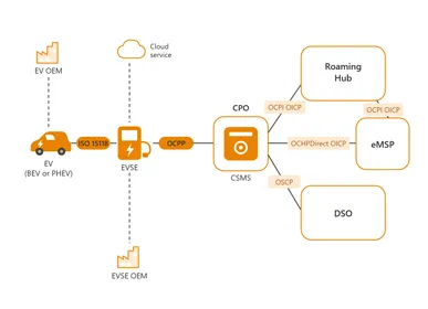
Check communication between the charger and the central management system through the configured network connection.
Important functions include:
OCPP communication and charger identification.
Online and offline status reporting.
RFID card or mobile application authentication.
Payment authorization and transaction records.
Charging session start and stop commands.
Energy consumption and billing records.
Fault notifications and remote monitoring.
The Open Charge Alliance OCPP protocol documentation provides information about standardized communication between charging stations and central management systems.
A final end-to-end charging session should be completed to verify that authorization, charging, session termination, and transaction recording work together.
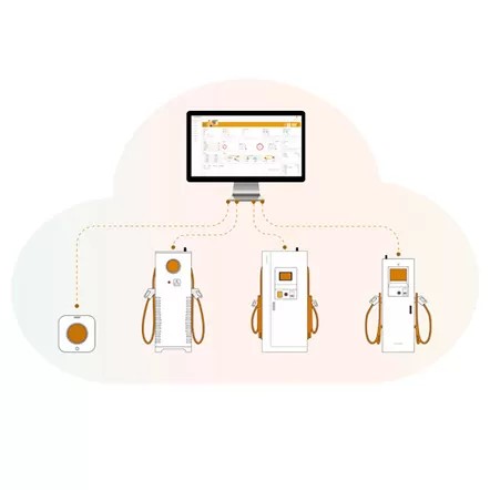
Use the following table to record the acceptance status of each test before approving public operation.
Test Item | Main Verification | Acceptance Record |
Documentation | Datasheets and certificates | Verified |
Physical installation | Mounting and cable condition | Passed / Failed |
AC supply and grounding | Voltage, phase, PE connection | Measured |
Electrical protection | Safety functions and emergency stop | Passed / Failed |
Insulation testing | Insulation and protective conductor | Recorded |
Connector inspection | Cable, contacts, locking | Passed / Failed |
Vehicle communication | Handshake and authorization | Passed / Failed |
DC output | Voltage and current performance | Measured |
Simultaneous charging | Power sharing | Verified |
Backend and payment | OCPP, transactions, remote control | Passed / Failed |
All test results should be documented, including instrument details, measured values, test conditions, corrective actions, and the responsible technician's approval.
Any failed safety-critical test must be resolved and successfully retested before the affected equipment is released for public operation.
DC fast charger commissioning is essential for confirming that a newly installed public charging station is safe, functional, and ready for commercial operation. Testing should cover electrical protection, grounding, connector condition, vehicle communication, DC output performance, power allocation, and backend connectivity.
For charging station operators and project developers, a documented commissioning process helps reduce operational risks and provides a reliable basis for equipment acceptance. Selecting equipment with appropriate technical documentation, protection functions, and manufacturer support also makes commissioning and long-term operation more manageable.
Commissioning time depends on charger power, installation complexity, network integration, and the number of charging points. A complete site may require several hours or longer for testing and corrective work.
Qualified electrical technicians and trained commissioning engineers should perform the tests in accordance with local regulations and manufacturer procedures.
IEC 61851-1 and IEC 61851-23 are important standards for EV conductive charging equipment. Additional national electrical regulations and measurement requirements may also apply.
No. A successful charging session alone does not verify grounding, electrical protection, output accuracy, emergency stop functionality, or backend integration.
Common equipment includes electrical installation testers, calibrated multimeters, insulation testers, EVSE communication simulators, DC load equipment, and network diagnostic tools.
Safety-critical failures must be corrected and retested before operation. Any unresolved issue affecting electrical safety, charging reliability, or legal compliance should be assessed before the station is released.
 English
 Deutsch
 Español
 italiano
 русский
 português
 Svenska
 العربية
 Nederland
 norsk
 français