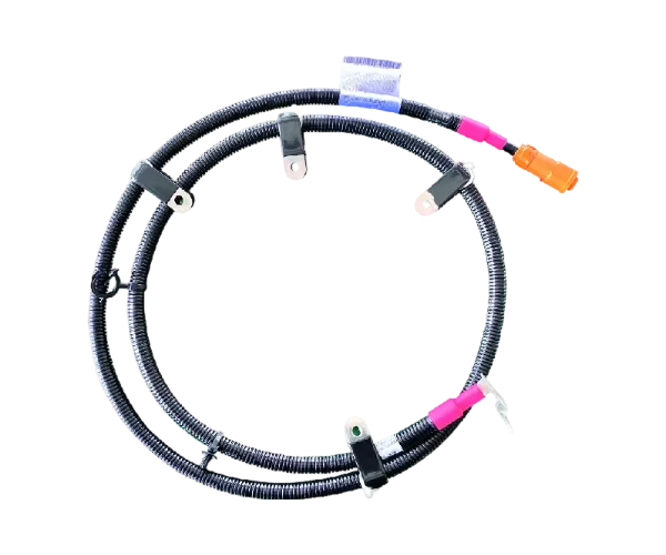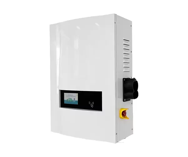
A 360–400 kW EV charging site is designed for high-power charging where vehicle throughput, short dwell times and future demand justify substantial electrical infrastructure. Successful planning requires more than selecting a high-output charger: operators must assess grid availability, vehicle compatibility, peak demand, site layout and expansion costs before installation. For developers and commercial operators, early planning can help avoid grid upgrades that arrive too late or equipment that cannot deliver its intended performance.
A 360–400 kW EV charging site is a high-power charging installation planned around vehicle energy demand, turnaround time and available electrical capacity. It may suit busy public charging hubs, fleet facilities or highway locations where vehicles need substantial energy during short stops.
Rated charger output is not the same as energy delivered during every session. A 400 kW charger can theoretically deliver 200 kWh in 30 minutes if it sustains full output throughout the session. Actual delivery depends on vehicle acceptance limits, battery state of charge, temperature, charging curves and system losses. Many vehicles cannot accept 360–400 kW continuously.
Demand planning should start with vehicle types, expected sessions per day, average energy required per visit and peak arrival patterns. The International Energy Agency’s Global EV Outlook 2025 provides global context on charging deployment and the development of fast-charging infrastructure. Site-level forecasts should still be based on local traffic, fleet schedules and realistic utilization assumptions.
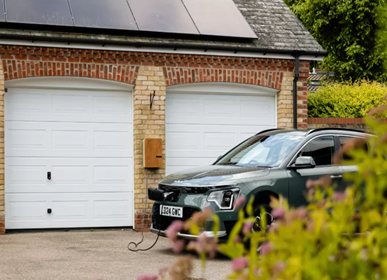
Grid capacity is the electrical power available to operate chargers and other site loads without exceeding utility, transformer or installation limits. One 400 kW charger can require more than 400 kW of grid input once conversion losses and auxiliary consumption are included, so the final design must use the equipment's rated input specifications.
| Site configuration | Combined rated charger output | Key planning consideration |
|---|---|---|
| 1 × 360 kW | 360 kW | Confirm service capacity and future demand |
| 1 × 400 kW | 400 kW | Check input demand and vehicle compatibility |
| 2 × 360 kW | 720 kW | Assess simultaneous charging and load management |
| 2 × 400 kW | 800 kW | Plan for a larger grid connection or controlled power allocation |
These figures show combined rated output, not the exact grid connection size required. Final capacity depends on charger efficiency, power factor, existing building loads, operating strategy and local electrical rules. A qualified electrical engineer and utility provider should assess transformer capacity, switchgear, protection, cable sizing, earthing and the connection timeline.
The IEC 61851-1 standard for conductive EV charging systems covers general requirements for EV supply equipment, including operating conditions and electrical safety. Applicable editions and local regulations should be confirmed for each project.
Vehicle demand is the expected quantity and timing of charging sessions at a site, including the energy each vehicle needs and how demand varies throughout the day. A site with a high daily energy requirement may still need less peak power if arrivals are spread across many hours; clustered arrivals can create a much higher peak.
Plan the number of charging bays around vehicle flow, turning space, cable reach, accessibility, traffic separation and maintenance access. Include space for electrical rooms, transformers, switchgear and any required cooling or protective equipment. For a fleet depot, match charger availability to departure deadlines; for a public hub, consider queue length and how long drivers are likely to stay.
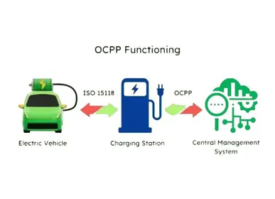
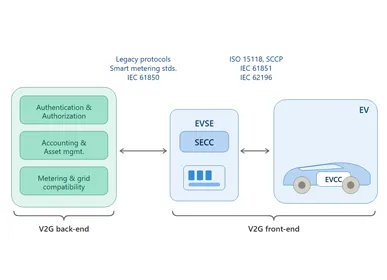
Vehicle-to-charger communication also matters when selecting compatible equipment and digital features. The ISO 15118-20 standard specifies communication between electric vehicles and charging equipment, including requirements related to power transfer. Confirm the supported functions across the intended vehicles, chargers and software instead of assuming interoperability is automatic.
Scalable charging infrastructure is a site design that allows additional chargers or greater power capacity to be added as demand grows. Expansion planning can reduce future disruption, but installing maximum capacity immediately may tie up capital before utilization supports it.
Reserve suitable space for additional bays, conduits, cable routes, switchgear and transformer upgrades where practical. Evaluate whether dynamic load management can allocate available power among chargers according to demand and departure priority. For example, two 400 kW chargers do not necessarily need to operate at full output simultaneously if vehicles can be charged sequentially within their parking windows.
AUPINS provides high-power charging options, including the EF400 Series 360 kW/400 kW DC quick charger. Operators can also explore the broader EV charger product range to compare charging equipment and configurations, or review EV charging accessories when planning compatible cables, adapters and connection components.
When evaluating equipment, compare output ratings, vehicle compatibility, cooling, communications, service support and installation requirements against the site plan. Requesting a quotation with the expected vehicle mix, operating hours, target utilization and expansion timeline helps suppliers recommend a configuration grounded in actual demand.
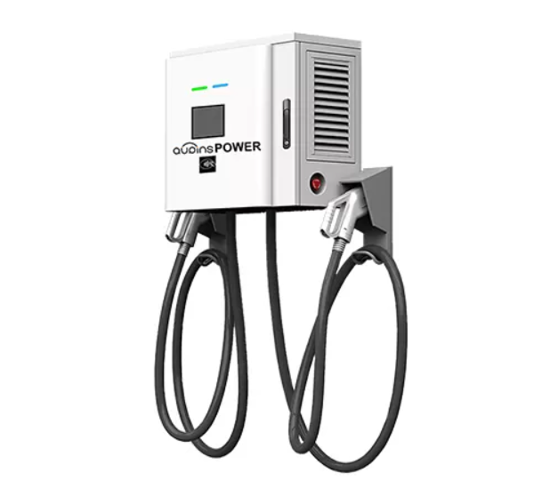
Planning a 360–400 kW EV charging site requires coordinated decisions about grid capacity, vehicle demand, electrical safety, layout and future growth. Start with realistic energy and arrival forecasts, verify the vehicles’ charging limits, and obtain a utility assessment before fixing equipment quantities. A scalable design can support growth while reducing the risk of paying upfront for power the site cannot yet use.
No. The vehicle's maximum charging rate and battery conditions determine how much power it can accept.
The theoretical figure is 200 kWh at constant full output. Actual delivery is affected by vehicle limits and charging conditions.
Not necessarily. Input demand, conversion losses, auxiliary loads and other site loads must be considered in the electrical design.
Yes, where the system supports suitable load management. The design must still meet vehicle energy needs and departure schedules.
Review utilization, peak demand, grid connection limits, reserved space, cable routes, switchgear and the cost and timeline of future upgrades.
Involve the utility during feasibility planning, before finalizing the charger count and layout. Grid upgrades and connection approvals can affect project cost and schedule.

 English
 Deutsch
 Español
 italiano
 русский
 português
 Svenska
 العربية
 Nederland
 norsk
 français